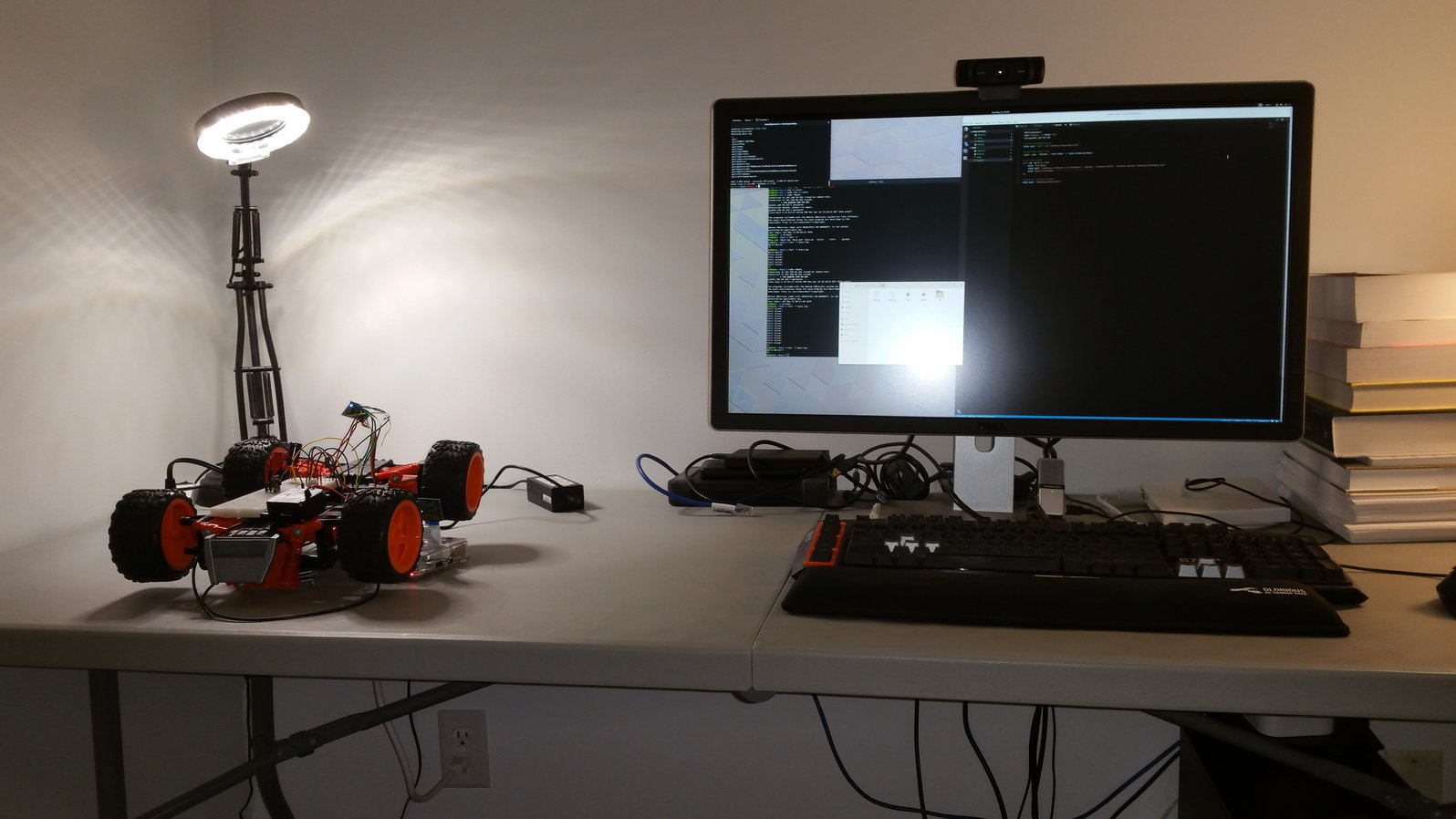
I have been waiting for a cheap, versatile, and easily programmable robot for years now. In a sense, my aspirations to own a robot are a promise to myself: I have always had the vague hope that once I get a real robot, I will somehow figure out how to endow it with intelligence! I mean, Atari games are great, but they are a limited sandbox. I want to see my learning algorithms run in the real world, on something I can interact with!
This is not as simple as it might seem, because you can’t just let a robot try random crap until something works in real life! Not only would it take forever for it to learn anything, but if it tried something bad, you would have a broken robot on your hands - or worse, a broken human! A real robot is the ultimate test of a learning algorithm: there is no way to cheat, and learning must happen through a mechanism more sophisticated than learning by dying repeatedly!
Whatever the case may be, to begin playing with robots, you need a robot. The classic robot is Nao, a $9,000 humanoid. Well outside a grad student’s budget.
Since I didn’t see anything endearing within my budget ($500), I decided to build one myself. I decided that I needed:
- A camera for vision
- Wifi, to offload computation to a powerful server
- Fully programmable onboard computer
- A gripper arm to carry things
- Microphone and speakers for audio
This is part 1 of a (hopefully) 3 part series on building and programming a robot out of an RC car. Right now, the plan is:
- Part 1: Building the car (this post!)
- Part 2: Programming the car
- Part 3: Making it Learn
While this post is written in a tutorial-like format, I recognize that everyone building a robot does it their own way, so the hardware is described from a high-level perspective. The software is described in a bit more detail, since it can be more-or-less the same across robots.
The Chassis
I do not have the equipment necessary to design and build a robot from scratch. Lacking a 3D printer and CAD skills, I decided to buy a nice RC car, the Maisto Baja Beast ($70), and to replace its brains.

Since this was a leisure project, there wasn’t much planning going on: I simply decided to buy the RC car in hopes that it would prove easy to hack. After playing around with it for a couple days (the thing is fast), it was time to pop the hood, and see what could be done about making it a real robot!
Unfortunately, I don’t have a picture of the original circuitry, but it was immediately obvious that there were 2 main problems:
- All of the motor controllers and logic were on a single monolithic circuit board
- The steering servo used some weird non-standard 4-cable interface.
It became clear that I would need to replace the main circuit board entirely, which means buying a new motor controller.
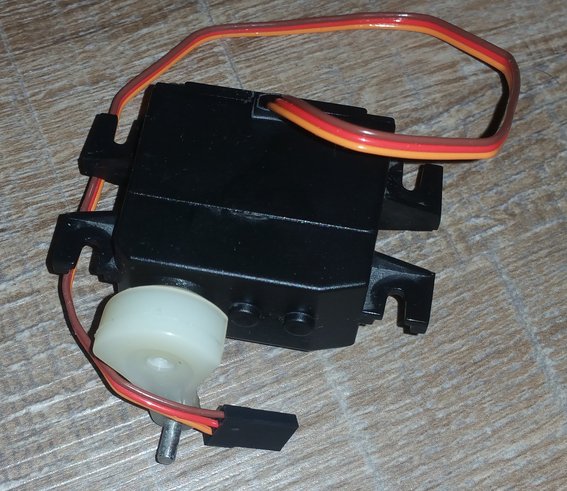
The steering servo was a bigger issue: the enclosure was custom-built to fit the car, so no off-the-shelf servo would work without serious surgery. I didn’t want to mess around with coding my own servo controller, so I needed it to have a standard 3-pin interface. In the end, I purchased a cheap $10 standard servo, and did a full-on transplant of motor, potentiometer and controller into the enclosure and gearing of the original. This was a gooey process, since servo gears have lubricating goop on them, but it resulted in a servo that can easily be controlled from an Arduino, and fits perfectly onto the chassis.
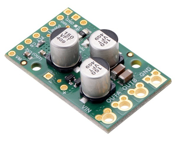
With the servo problem solved, I got a tiny high-power motor driver ($40) to control the main motor. Finally, to send the raw PWM signals necessary to control motor and all servos aboard the robot, a super-cheap Arduino clone ($5) was used:
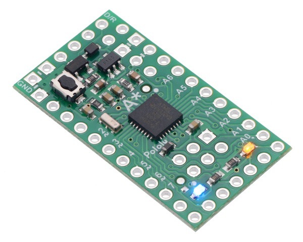
Once I added a 5V 1A DC/DC switching converter to convert battery voltage to the 5V needed by the Arduino and servo ($5), a quarter-sized proto-board (
At $134 already, this was not cheap, especially since I was just getting started. With a weaker motor controller or cheaper RC car this price could have been greatly decreased, but it’s still a far cry from the thousands of dollars a “professional” robot would cost.
Sensors
The drive-train afforded the robot mobility, but no way to sense anything about its environment. To fix this, I added a basic suite of sensors:
- Ultrasonic range sensor ($4) - allows to sense distance from a wall
- Accelerometer ($10) - can be used to tell the robot how it is moving (I used an older model I had laying around)
- Temperature Sensor ($2) - eh, why not? It’s cheap.
- Current Sensor ($4) - gives info on how much juice the robot is sapping from the battery
- Voltage Divider (2 resistors) - Battery level can be estimated from its voltage. Since the Arduino runs on 5V, and the battery can be up to 10V (a capacitor I used has a 10V limit), I needed 10V on the battery line to correspond to 5V on the sensor portion of the divider, allowing the Arduino’s analog input to measure battery voltage. That meant that I could use 2 equal-valued resistors ($1).
At a total cost of about $21, the sensors were a cheap way to get basic input about the world. These are all secondary, however, because the main input sources for the robot are video and audio, bringing me to the robot’s main computer.
Brain
The Raspberry Pi is the perfect robot computer: cheap, has built-in wifi, has an official camera, and most importantly, has a huge community with tons of examples. If you have a problem with the Pi, the answer is ususally a quick google-search away.
So… with a Raspberry Pi 3B ($35), the Pi Camera ($25), an SD card ($12), and a case ($8), I was off to the races!
… Almost. There were two more things I needed to take care of to allow the Pi to interface with the robot:
- Since the Pi needs a max of 2A at 5V, and the robot was to be powered by battery, I needed an UBEC DC/DC Converter ($10), which gives the Pi the power it needs.
- The Pi GPIO output pins run on 3.3V logic, while the Arduino runs on 5V. In order to allow the Pi to communicate with the Arduino, a logic-level converter ($3) is needed. With this, and some clever cabling, the Arduino is programmable directly from the Pi.
Finally, I wanted the robot to be able to hear and speak, so a usb microphone ($3) and a speaker ($5) were necessary.
At a total of $101, giving the robot a brain turned out nearly as expensive as the chassis.
Arm
To really interact with the world, a robot needs hands. Robot arms are super expensive in general, but it turned out that I could get a (very) basic robot arm, the MeArm - Robotic Arm Maker Kit for $40.
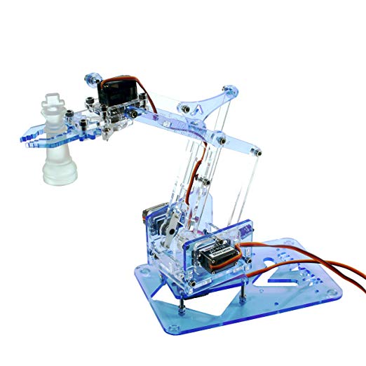
The nice thing here is that it is controlled by 4 standard servos (included), so there was no issue interfacing it to the Arduino. The only extra stuff really needed were 2 more 1A 5V DC/DC converters (
This brought the arm’s total cost up to $51.
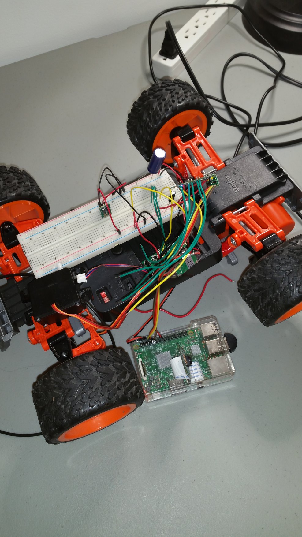
Building The Chassis
Once the parts were ready, it was time to put it all together. Since I was planning on using a LiPo battery, I could use the RC car’s battery compartment on the bottom of the chassis to fit the electronics.
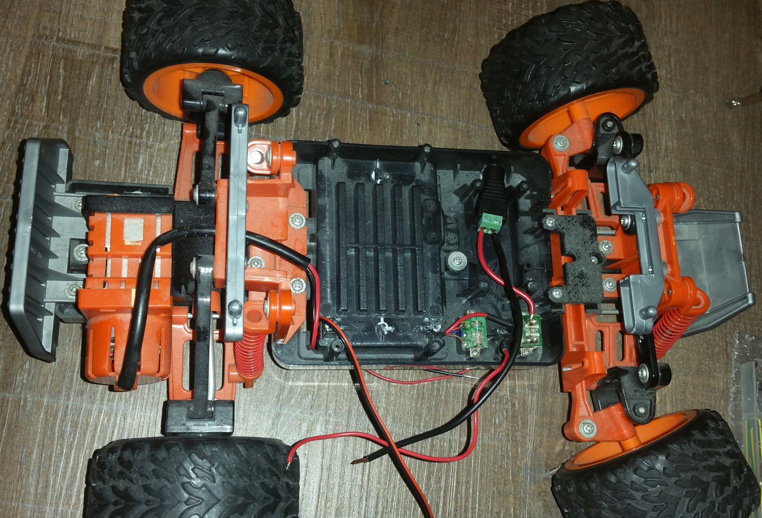
To start off, the main power distribution was put into place. This was the second most difficult part of the whole project, since it required soldering motor wires and UBEC as well as the current sensor with minimal space (the whole thing needed to fit in a corner of the compartment).
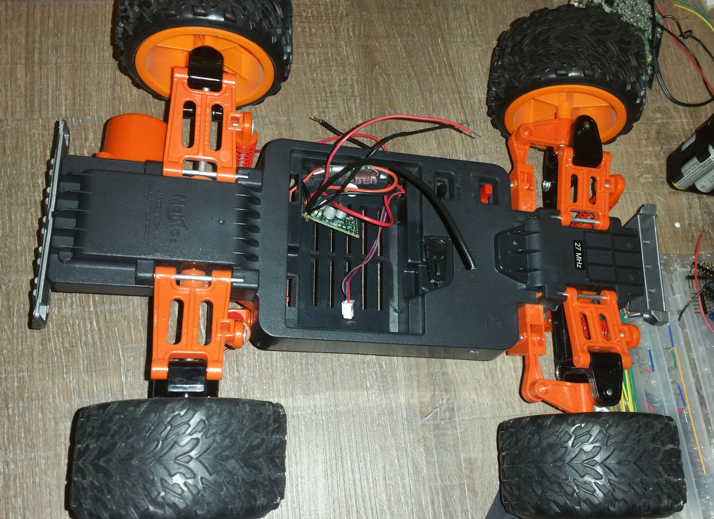
I also decided to add a plug to the power distribution so that the robot could be wall-powered when not on battery. I wired it to the ON-OFF switch built into the chassis, so that when in the ON position, the robot gets power from battery, and when OFF, it gets powered by the wall adapter.
This was a spur-of-the moment decision that made my life much easier. Not only did it allow debugging stuff without worrying about battery, but it also enabled switching out batteries or charging without turning off the robot: all I need to do is plug it in while on battery, flip the OFF switch, and the robot is wall-powered!
It involved getting the plug shown in the below picture (
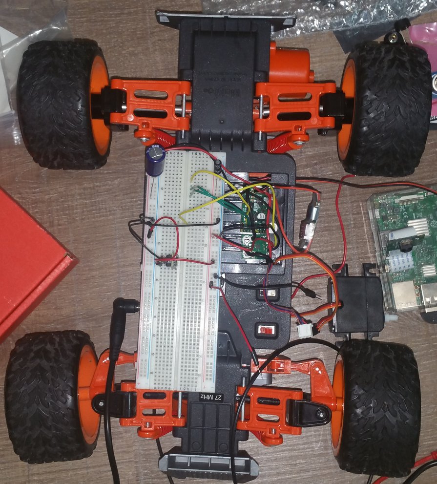
To make sure that the motor controller and servo were working, I set up a basic test on a breadboard, using a standard Arduino Uno I had laying around, powered using the robot’s power delivery.
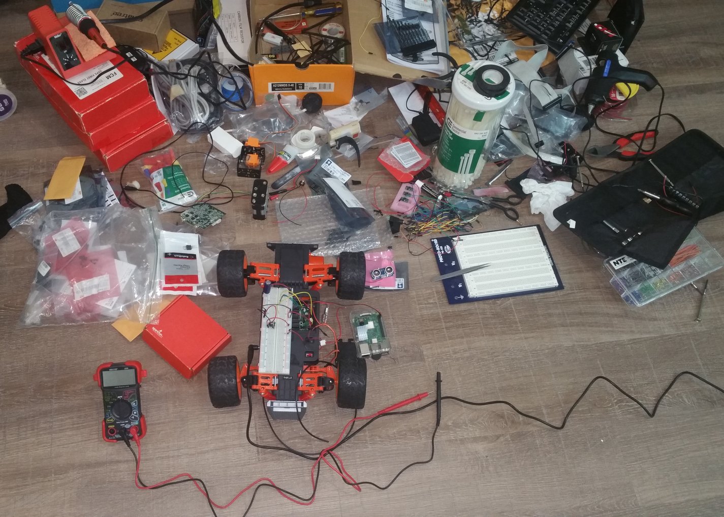
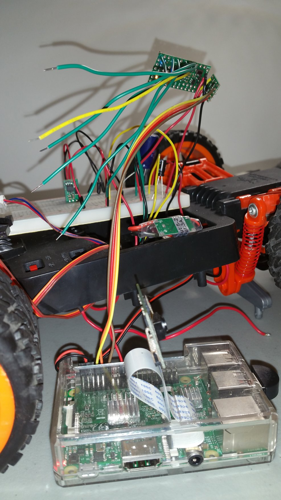
During this part of the build process, my apartment was a mess, with various parts strewn around the floor. Each time I came home from the office I had to be careful not to step on a sensor or chip:
Having tested the motor and power delivery, it was time to wire up the Arduino, and interface it with the Pi
Programming & Computer Interface
I will now do a brief dive into how I set up the computer, including how to program the Arduino directly from the Pi, and how to program the whole robot from a standalone computer.
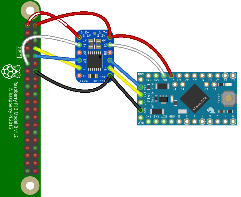
The first step is connecting the Pi to the Arduino so that the two can talk. Since the Pi works off of 3.3V, but the servos and Arduino operate at 5V, I required a level shifter which can convert between the two logic levels.
Connecting and Programming the Arduino
The Pi’s pinout is available at pinout.xyz. I connected 3.3V to the level shifter’s input, 5V to the other side of the level shifter and to the Arduino, and TX/RX to RX/TX. I also connected the Arduino’s reset pin to BCM 17 on the Pi, which was to be programmed to send a reset signal at the correct time when uploading new code to the Arduino.
Before connecting this up, the hardware serial port needed to be enabled on the raspberry pi. This can be done by running:
sudo raspi-config…and finding serial in the Interfaces menu. Once prompted, I had to to say NO to the login shell, and YES to the hardware serial port.
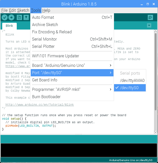
At this point, it was time to download and install the Arduino software. As of writing, the version available in standard repositories is very old. To make sure things will work, the best approach is to download the official ARM build, and install that as is. Once installed, I set up the necessary libraries and details (The Astar requires some special setup).
The hardware serial showed up as the port /dev/ttyS0. To get permission to use it, I needed to add pi to the dialout group:
sudo usermod -a -G dialout piA reboot was needed for this setting to take effect.
Unfortunately, I wasn’t done yet. You see, in order to be programmed, the Arduino needs to be rebooted at just the right time so that the programmer can signal the bootloader to upload new code. This is done automatically when programming a USB Arduino, but since I was manually wiring up the pi to Arduino pins, I had to hijack this procedure to fire the reset pin at the correct time.
Luckily, other people have had this problem before, and I exploited their solutions. In particular, avrdude-rpi is a hack that finds when avrdude, the pi’s programmer, wants to reboot the Arduino, and manually toggles the Pi’s pin that I have wired up to the Arduino’s reset!
This means that all I needed to do is replace the Arduino software’s avrdude binary with a special script that listens to the binary’s execution, and toggles pin 17.
First, I modified the autoreset script to fire the right pin:
...
 fl = fcntl.fcntl(fd, fcntl.F_GETFL)
 fcntl.fcntl(fd, fcntl.F_SETFL, fl | os.O_NONBLOCK)

-GPIO.setmode(GPIO.BOARD)
+GPIO.setmode(GPIO.BCM)
 dtr = re.compile('.+TIOCM_DTR.+')
 start = time.time()

 def reset():
-  pin = 11
+  pin = 17
   GPIO.setup(pin, GPIO.OUT)
   GPIO.output(pin, GPIO.HIGH)
   time.sleep(0.12)
...
If you are trying this, you can make sure it resets the Arduino by calling reset() instead of process() at the end of the file, and seeing if the Arduino reboots (just make sure to switch it back!).
Then, I went to the install directory for Arduino’s avrdude binary: ~/.arduino-1.8.5/hardware/tools/avr/bin, renamed avrdude to avrdude-original, and replaced it with the script that comes with avrdude-rpi, making sure to change the path of avrdude-original in the script to /home/pi/.arduino-1.8.5/hardware/tools/avr/bin/avrdude-original (also, chmod +x the script to made it executable).
Finally! With that finished, I was able to upload code from the Arduino UI as if it were a standard USB-connected Arduino!
Obviously, I wasn’t going to be using the GUI to reprogram the Arduino each time! Thankfully, the arduino executable enables a headless mode, allowing me to compile and upload from command line:
/home/pi/.arduino-1.8.5/arduino --upload --verbose-build --verbose-upload /home/pi/myscript.inoThis was exploited to program the robot remotely…
Remote Reprogramming
I wasn’t about to connect a monitor and keyboard to the robot each time I wanted to change some onboard code. Instead, I used ssh and rsync with some simple scripts to enable programming from a computer connected to the same network as the Pi.
The first order of business was connecting the pi to wifi, going into the router’s settings, and giving the Pi a static IP. This made it have the same address each time the robot turns on.
Next, I created a folder, /home/pi/baja which houses all of my code. On my external computer, I installed sshpass, which allows passing in an ssh password in bash scripts.
To make life simple, the process of logging into the Pi, uploading code, and running the code was split into several tiny bash scripts.
To start off, I created a bash script called cred, which contains login credentials to the Pi:
#!/bin/bash
# cred

PASS=raspberry # Password
SSH="sshpass -p $PASS ssh" # The ssh command
LOC=pi@192.168.1.182 # IP of the Pi
Using the above script, I created a second, connect script, allowing super quick ssh access:
#!/bin/bash
# connect

source ./cred
$SSH $LOC
With that out of the way, I created the python file housing the actual code which runs on the robot to control it. For the moment, I made baja.py an infinite loop:
import time
i=0
while True:
    print(i)
    i+=1
    time.sleep(1.0)
This code is meant to always be running. I added a quick start script to get it started:
#!/bin/bash
# start
# This is run on startup

cd /home/pi/baja
nohup python3 -u baja.py &> baja.log < /dev/null &
echo $! > baja.pid
The above simple start script does 2 things:
- It sends all of the output of
paja.pytobaja.log, so that I can debug it remotely - It saves the PID of the running script to
baja.pid, so that the script can be restarted remotely
I wanted this script to run on boot, so I added it to /etc/rc.local:
# Start the baja software as user pi
sudo -u pi /home/pi/baja/start
Having run the start script, I went back to the full computer, and created a script that outputs the log (called catlog)
#!/bin/bash
# catlog

source ./cred
$SSH $LOC "tail -f /home/pi/baja/baja.log"
With this script in hand, I could see what was going on with the robot by simply running ./catlog, and getting a stream of output on my remote computer.
And now, the most important script: upload
#!/bin/bash
# upload
source ./cred

# Stop running program
$SSH $LOC 'kill `cat /home/pi/baja/baja.pid`'

# Sync the files over
rsync -avz --delete --rsh="$SSH" ./ $LOC:/home/pi/baja/

# If args given, reprogram the Arduino
if [ $# -gt 0 ]; then
    echo "Building"
    $SSH $LOC "/home/pi/.arduino-1.8.5/arduino --upload --verbose-build --verbose-upload /home/pi/baja/Baja.ino"
    echo "\nBuild Finished -----------------------------"
fi

# Restart running program
$SSH $LOC "/home/pi/baja/start"
This script stops the currently running code, syncs the current folder to the pi, uploads Baja.ino to the Arduino if given an argument, and restarts the python code.
That means that no matter what was happening on the robot, ./upload would update the code to the stuff on my computer. If I also wanted it to reprogram the Arduino, I could run ./upload r (give an argument to the upload script).
Last but not least, a script to safely turn off the pi:
#!/bin/bash
# stop

# This script shuts down baja.
source ./cred
$SSH $LOC "echo $PASS | sudo -S shutdown -h now"
With the above scripts, I could do all coding at my own computer, upload with ./upload, debug with ./catlog, and run commands with ./connect.
Talking to the Arduino from Python
In the above two sections, the Arduino was set up for programming and communication with the Pi, and a python script was set up to run on the Pi. Now, I wanted the Arduino and Python script to talk to each other! This allowed for controlling servos and getting sensor readings from Python code.
To achieve this, I installed python-serial on the pi, and used the following code:
// baja.ino
// Run once at startup
void setup() {
    Serial.begin(115200);
}

// Run in a loop
void loop() {
    Serial.println("Hello!");
    delay(1000);
}
# baja.py
import serial
s = serial.Serial("/dev/ttyS0", 115200)
while True:
print(s.readline(), sep="")After uploading this code with ./upload r, I saw the “Hello!” message pop up once a second under ./catlog.
This is all of the programming that I will describe for now. Full programming of the robot will need to wait for part 2 of this post series! You can download a zip file of all the code mentioned above right here.
Finishing the Build
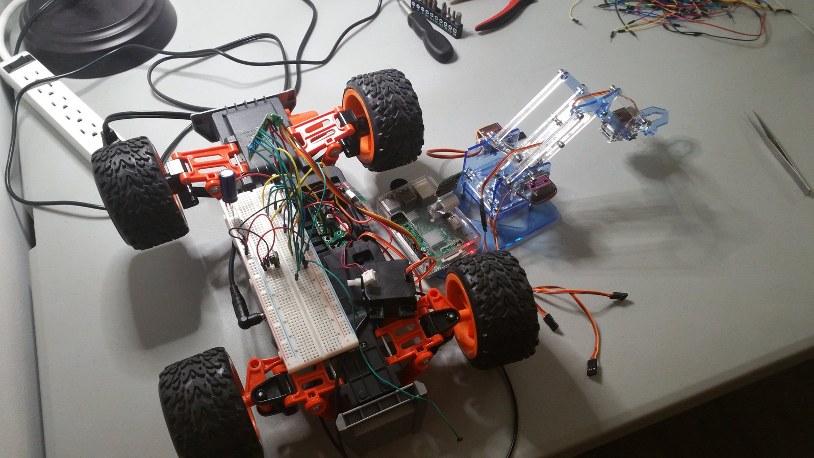
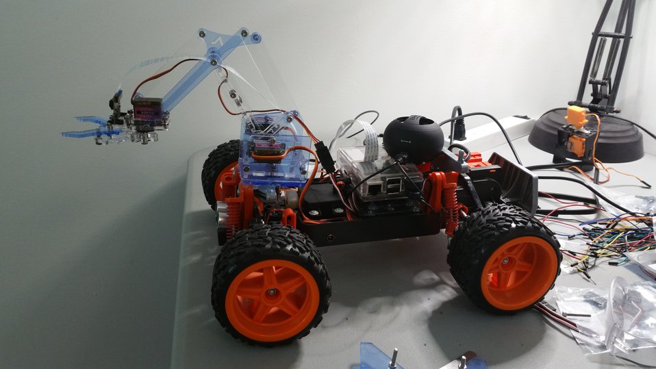
Now that I had the robot’s computer set up, it was time to finish up the hardware! First order of business was to build the robot arm, and make sure I could control it from the Arduino:
Next, it was finally time to lose the breadboard, and start putting down some components permanently!
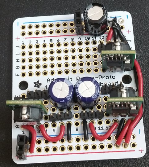
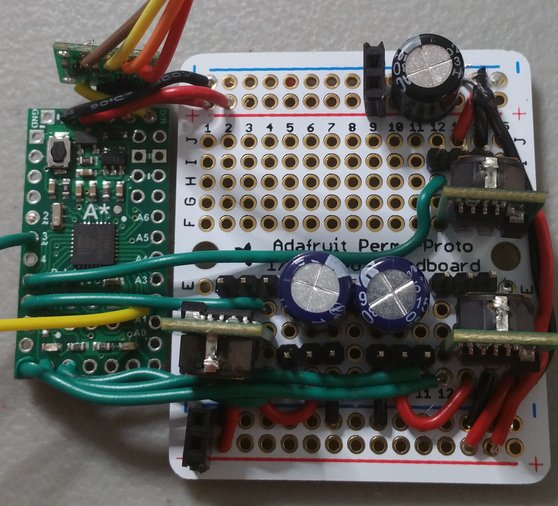
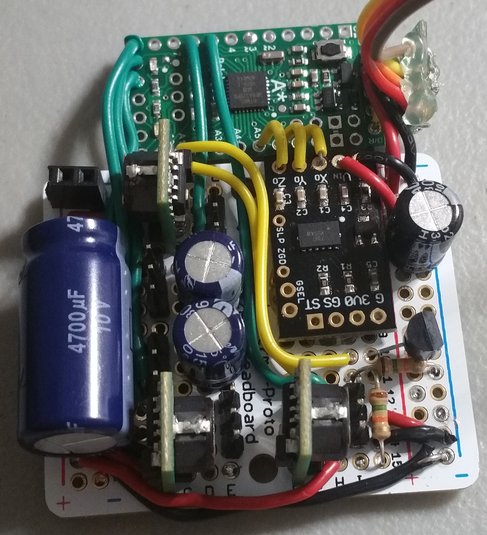
While this looks complex, it is really a byproduct of my using multiple weak DC/DC converters - all you actually need is a capacitor and a good source of 5V current to run servos. To this, I added the temperature sensor, a voltage divider, and an accelerometer. The rest is just routing wires where they need to go.
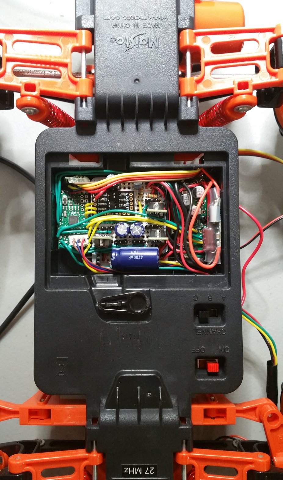
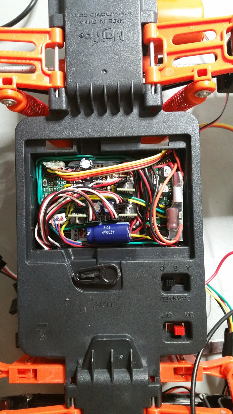
Once the main board was done, it became time for the most difficult part of the whole build: wiring everything together with power and motor controls inside that tiny battery compartment:
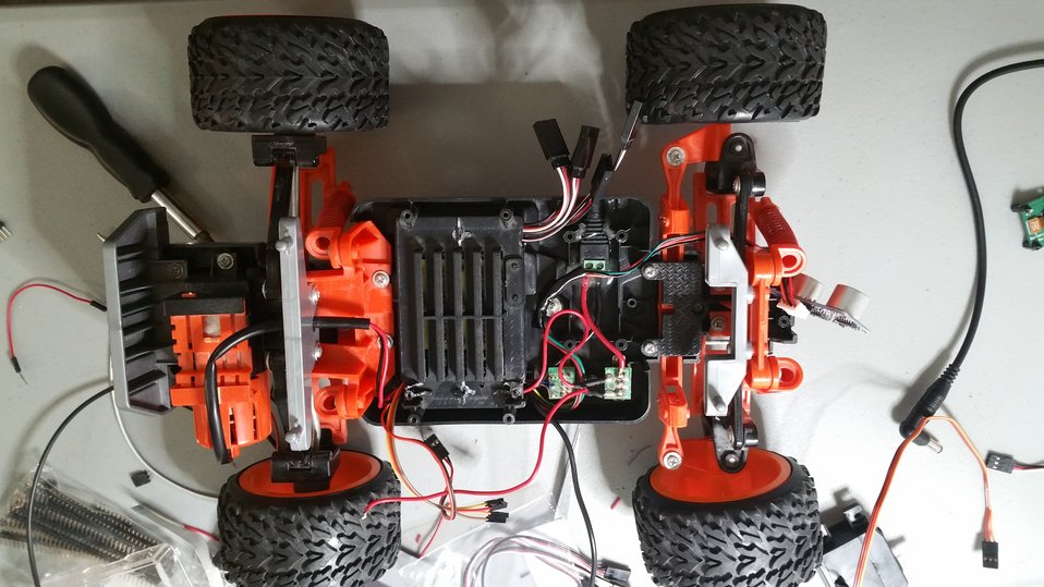
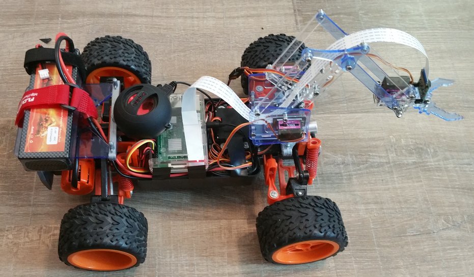
With that, the robot was basically finished. All that it needed was a bunch of hot glue to attach the Pi and robot arm:
Battery
Finally, it was time to buy the last component: the battery. It turns out those are super expensive!
I ended up getting a LiPo RC Battery ($40) as well as a LiPo Battery Charger ($50). With this battery, the robot can slowly trudge around for several hours before needing to recharge.
With a functioning battery attached, everything was ready - the robot was awaiting its programming, which will be the subject of the next part in this series!
Summing Up
Starting this project, I hoped that I could build something super cheap. This turned out not to be the case:
| Item | Cost |
|---|---|
| Chassis | $134 |
| Sensors | $21 |
| Computer | $101 |
| Arm | $51 |
| Battery | $90 |
| Misc | ~$40 |
| Total | $437 |
While it was still priced well below existing products, that doesn’t include the hours of work put into figuring out how to actually build it!
Nevertheless, I now have a robot. Once I find some time, I will write up a post on actually controlling the thing!